On the OBD1 plugs the wiring scheme is like this (according to the Honda service manual):
On the OBD2 plugs the wiring scheme is like this (according to the Honda service manual):
OBD 2 To OBD1 Conversion Harness
This page copied with permission from Trever Cobb, his site can be found here: http://t24ever.com/
K... Here is the promised 99-00 OBD2 to OBD1 (P28) conversion info I promised. Umm... My harness is made to convert an OBD2 (99-00) engine harness (Civic EX, Si, Integra Type R) into an OBD1 harness for use with a P28 (92-95 SOHC VTEC) ECU that has been chipped. These ECUs do not have support for a knock sensor, secondary o2 sensor, crank fluctuation sensor and some other evaporative stuff that didn't exist from 92-95. If you use an OBD1 ECU that needs to have a wire for the knock sensor you will need to figure out where the wire goes on the OBD1 end of the harness. From the OBD2 end it comes from (C3) right next the white/yellow wire going into (C2) and the orange/black wire going into (C1). Edit by Solblu Knock sensor wire added to the table.
I built my converter harness by taking my stock 99 CX ECU and using a grinder to detach the plastic plug/pin part (what else do you call it?) from the circuit board. There are three screws holding it to the board. All three have solder on top of them that if you grind off first you will see the phillips screw head underneath and be able to unscrew it with a small screw driver. We also used the grinder on the underside of the circuit board to basically de-solder the pins from the circuit board.
I bought some 95 Del Sol ECU Plugs (SOHC VTEC) from a local junkyard. I cut the harness about a foot up from the plugs so I had plenty of length on the wires coming out of the plugs.
I then did my research (see my chart below) and got started soldering. It was kind of a bitch to do because the pins are so close together. I realized I needed a way to cover the exposed metal on the wires and pins as well as the solder I was globing on, so I went to a local hardware store and bought several packages of the smallest heat shrink tubing I could find. Then I cut the little tubes to the length I needed, slid them down the wires and after I soldered each one I slid the tube up to cover the exposed metal then used a hairdryer to heat the tubing and make it shrink. It ended up pretty clean looking and I don't have to worry about anything shorting out.
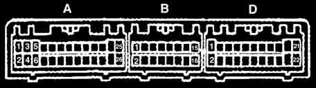
On the OBD1 plugs the wiring scheme is like this (according to the Honda service
manual):
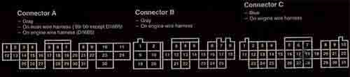
On the OBD2 plugs the wiring scheme is like this (according to the Honda service
manual):
Here's the crossover list with corresponding OBD1 plug colors:
|
Function |
99-00 Civic ECU |
92-95 Civic ECU |
92-95 ECU |
|
|
A1 |
|
|
|
|
A2 |
|
|
|
|
A3 |
|
|
|
|
A4 |
|
|
|
|
A5 |
|
|
|
PCS |
A6 |
A20 |
Red |
|
|
A7 |
|
|
|
|
A8 |
|
|
|
|
A9 |
|
|
|
SCS |
A10 |
D4 |
Brown |
|
|
A11 |
|
|
|
|
A12 |
|
|
|
|
A13 |
|
|
|
|
A14 |
|
|
|
|
A15 |
|
|
|
FLR |
A16 |
A7 |
Green/Yellow |
|
ACC |
A17 |
A15 |
Black/Red |
|
MIL (CEL) |
A18 |
A13 |
Green/Orange |
|
TACH |
A19 |
A21
|
Red/Green ** |
|
FANC |
A20 |
A12 |
Yellow/Green |
|
K-LINE |
A21 |
D7 |
Light Blue |
|
|
A22 |
|
|
|
|
A23 |
|
|
|
STS |
A24 |
B9 |
Blue/White |
|
|
A25 |
|
|
|
PSPSW |
A26 |
B8 |
Brown/Red |
|
ACS |
A27 |
B5 |
Blue/Red |
|
|
A28 |
|
|
|
|
A29 |
|
|
|
EL |
A30 |
D10 |
Green/Red |
|
|
A31 |
|
|
|
BKSW |
A32 |
D2 |
Green/White |
|
IGP1 |
B1 |
B1 |
Yellow/Black |
|
PG1 |
B2 |
A24 |
Black |
|
INJ2 |
B3 |
A3 |
Red |
|
INJ3 |
B4 |
A5 |
Light Blue |
|
INJ4 |
B5 |
A2 |
Yellow |
|
|
B6 |
|
|
|
|
B7 |
|
|
|
|
B8 |
|
|
|
IGP2 |
B9 |
A25 |
Yellow/Black |
|
PG2 |
B10 |
A23 |
Black |
|
INJ1 |
B11 |
A1 |
Brown |
|
VTS |
B12 |
A4 |
Orange/White |
|
ICM |
B13 |
A21 |
Red/Green |
|
|
B14 |
|
|
|
|
B15 |
|
|
|
|
B16 |
|
|
|
|
B17 |
|
|
|
|
B18 |
|
|
|
|
B19 |
|
|
|
LG1 |
B20 |
B2 |
Brown/Black |
|
VBU |
B21 |
D1 |
White/Blue |
|
LG2 |
B22 |
A26 |
Black/Red |
|
IACV |
B23 |
A9 |
Green/White |
|
|
B24 |
|
|
|
|
B25 |
|
|
|
P02SHTC |
C1 |
A6 |
Orange/Black |
|
ALTC |
C2 |
A16 |
White/Yellow |
|
KS (Knock) |
C3 |
D3 |
Red/Blue |
|
|
C4 |
|
|
|
ALTP |
C5 |
D9 |
Pink |
|
|
C6 |
|
|
|
SG1 |
C7 |
D21 |
Green/Blue |
|
CKPP |
C8 |
B15 |
Blue/Green |
|
CKPM |
C9 |
B16 |
Blue/Yellow |
|
VTM |
C10 |
D6 |
Orange/Blue |
|
|
C11 |
|
|
|
|
C12 |
|
|
|
|
C13 |
|
|
|
|
C14 |
|
|
|
|
C15 |
|
|
|
PH02S |
C16 |
D14 |
White |
|
MAP |
C17 |
D17 |
Pink/White * |
|
SG2 |
C18 |
D22 |
Green/White |
|
VCC1 |
C19 |
D19 |
Yellow/Green |
|
TDCP |
C20 |
B13 |
Orange/Blue |
|
TDCM |
C21 |
B14 |
White/Blue |
|
|
C22 |
|
|
|
VSS |
C23 |
B10 |
Yellow/Blue |
|
|
C24 |
|
|
|
IAT |
C25 |
D15 |
Red/Yellow |
|
ECT |
C26 |
D13 |
Red/White |
|
TPS |
C27 |
D11 |
Pink/Blue * |
|
VCC2 |
C28 |
D20 |
Yellow/White |
|
CYPP |
C29 |
B11 |
Orange |
|
CYPM |
C30 |
B12 |
White |
|
|
C31 |
|
|
*
These colors are what is listed in the factory service manual but they
did not match the actual wire colors of my cut OBD1 harness.
**
A wire needs to be tapped into the existing wire that goes from
B13 (OBD2 side) to A21 (OBD1 side), this wire will then go to
A19 (OBD2 side) to feed the tach the RPM signal it needs.